Serial 2 S Complementer Shift Register
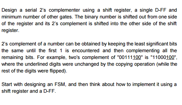
Design a serial 2's complementer with a shift register and a flip flop. The binary number is shifted out from one side and it's 2's complementer shifted in to the other side of the shift register.
Each stitch is hand tooled in this meticulous process that requires a high level of skills from the artisan. Only a few old school master boot makers still use this technique in Mexico, we are so lucky to have people in our workshop that helped us to preserve this beautiful technique dated from the very first western boot makers. Krossvord po menedzhmentu s otvetami. The 'Punto Marcado' Technique Punto Marcado is an Old Technique used in Mexico to embellish and secure the stitches on the welt that joins the welt to the Midsole or Outsole in the case of these western boots.
Hey guys, so the question reads: It is known that the 2's complement of a binary number can be formed by leaving all significant 0's and the first 1 unchanged and complementing all other higher bits. Design a serial 2's complementer using this procedure.

The circuit needs a shift register to store the binary number and an SR flip flop to be set when the first least significant 1 occurs. An XOR gate can be used to transfer the unchanged bits (x[xor]0=x) or complement the bits (x[xor]1=x'). So i understand all the components in the circuit, like the register, the xor gates, and the SR, but i have no idea about how to mesh them together to form this circuit Any help would be mucho appreciatedo!
Thanks for your kind reply See I have followed you and understood your line 39 to 51 is printable characters. In my case I have attached 74HC165 TO GET PARALLEL DISPLAY DATA FROM AN INSTRUMENT TO CONVERT IT INTO SERIAL AND THEREAFTER SERIAL DATA INPUT TO ARDUINO FOR DISPLAYING THE OBJECT OF THE INSTRUMENT INTO THE DISPLAY OF ARDUINO. AND THERE IS MY PROBLEM IN SPTE OF GETTING THE “INSTRUMENTAL DISPLAY OBJECT” i AM GETTING THE “011000” VALUE ACCORDING TO YOURS. WOULD YOU PLEASE BE ABLE TO GUIDE ME TO CONVERT THIS “011000” DATA TO ACTUAL DISPLAYING OBJECT?
THANKS FOR YOUR INFORMATION: THE ACTUAL DISPLAY OF THIS INSTRUMENT HAS BEEN DISCONTINUED AND THEREFORE i WANT TO TAKE THE DISPLAY DATA OF THE INSTRUMENT INTO ARDUINO THROUGH ON ITS LCD. From my understanding, you have the buttons well connected to the shift register and the output of shift register is also connected to the Arduino. If you are using the same display (16×2 HD44780 LCD), then the code above should have worked for you. If you are using other display, you may need to change to code for the display. Another thing that you can try is, first make sure you read what is exactly send from the shift register.
Change the code to display it using your serial monitor. From there, if you able to read the correct input from your buttons, then its just the display code you need to work on. Hope this helps.